Related Product
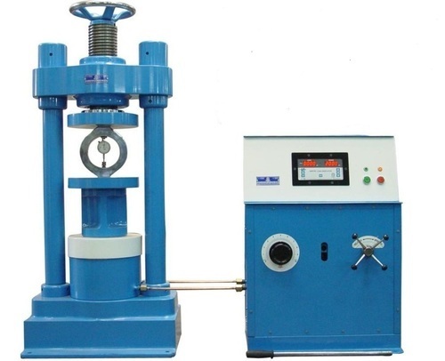
Universal Testing Machine
Universal Testing Machine (1000KN)
Technical Specification:
Should be suitable for doing testing experiments such as the tensile, compression, bending and shear testing for all kinds of metal materials and nonmetal materials such as plastic, concrete, cement and so on.
Should accord with the relative requirements of ISO, ASTM, JIN, GB and many other testing methods.
Should be ASTM E8, ASTM C39, ASTM F606, SAE J429, CE Compliant.
Frames should feature dual spaces so users can quickly change between tension and compression testing without having to remove heavy fixtures
Control console should be integrated with digital meter, hydraulic power pack, precise electronic loading regulator and unloading valves
Extra-length screws and columns, with an adjustable lower crosshead, to increase the available test space for longer test samples
Should be with digital displacement transducer for the best positioning and measuring accuracy.
Should consist of Main frame; Control console; Controller and sensor; Sample jaw three sets; Bend support saddle; Bend pressure energy; Spheric compression plate; Lower compression plate; Top board; Ground screw and nut; Inner hexagon spanner; wire power cord; O type gasket; Cruciform screw driver; Double offset ring spanner and Shearing accessories
Technical Parameter:
Max. Testing power: 1000KN or higher,
Testing power precision: Grade 1 (minimum),
Max. beam rising speed: 310mm/min .
Column number: 4
Max. Tension distance: 600 ~ 750mm,
Compress distance: 0-600mm or higher,
Clamp diameter of round specimen: Dia. 20-40mm or higher,
Clamp thickness of flat specimen: 0-40mm or higher
Clamp width of flat specimen: 80 ~ 90 mm ,
Size of compression plate: 200mm x 200mm (approx.)
Bending stick distance: 100 ~ 400 mm,
Bending Degree allowance: 150 ~ 200 mm
Main frame Parameter:,
Oil Pump power: 2.5KW or higher,
Supply: Standard Accessories /Equipment
Required Paper: Authorized Certificates from manufacturer, Operational Manual, catalogue must be enclosed.
Warranty: One year full warranty.
Installation: Must Complete with accessories by the bidder
Training: The bidder should arrange orientation training at SPI premises.
.jpg)
Mechanical Soil Compactor Brochure
Plate Compactor (SG90)
Engine Air-cooled, 4-stroke, single-cylinder Engine type Honda GX160 Diesel engine Weight 90KGS Frequency 4200VPM Centrifugal force 15KN Compaction depth 30cm Plate size 50*45cm Package 63*52*80cm Packing Hob and carton.
Shear Force & Bending Moments in a Beam
AirYa-Model: AYJ20241217E02
Specification: Dimensions 158 cm X 45cm X (h)60cm-160 cm X 46cm X (h) 61cm
Total Beam Length 160 cm with flexure
Width of Beam 5 cm
Distance of Length in Between 5 cm
Height of Beam 36 mm
No of Hanger for Weights 3
No of Spring Balance 2 (of 10kg)
Total Weight of Apparatus 13.1 kg
Two Spring Balances 10kgs |
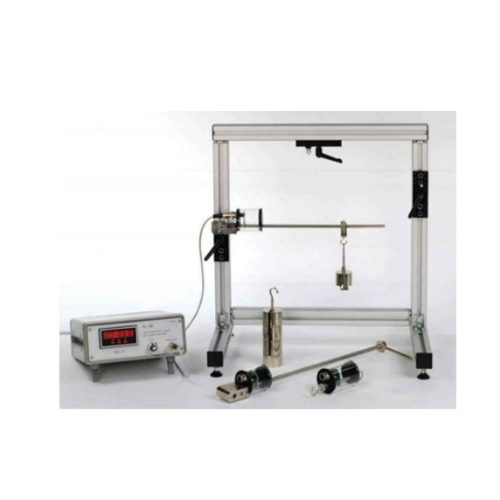
Deflection of Beam & Cantilevers
AFME013 Deflection Of Beams And Cantilevers
Technical Data: Steel Beam 25(W) x 5(H) x 1200(L) mm Digital Dial Gauge: 12.7mm travel; 0.01mm resolution Weights set: 10 x 1N, 20 x 2N, 1 x 50N 1 x Load hanger Structure: aluminum Bottom with adjustable rubber to adjust the height. ,The total weight is less than 200kgs.Working environment: -10℃~40℃, Humidity<85% Test beam – Steel 2Built-in/Knife Edge Support 2, Hanger sliders 2 ,Load hangers 2 ,Dial Indicators 2. Digital Indicator with digital output instead of Dial Indicators.
Bending Stress in a Beam
AirYa- AFME021 Bending Stress in a Beam
| | |
| | Specification: Beam: 900(L) x 51(H) x 25(W) x 3.2(t) mm
Loading Mechanism: 0-500N
Five pairs of strain gauges
Half Bridge Strain Gauging Typical Experiments Fundamentals of measuring with strain gauges Correlation between mechanical strain and electrical resistance in a strain gauge Calculation of the mechanical deformations under bending, torsion or combined bending and torsion III. Technical Data Structure: aluminum Bottom with adjustable rubber to adjust the height. The total weight is less than 200kgs. Working environment: -10℃~40℃,Humidity<85% |
Bernoulli's Theorem Apparatus
AirYa-AYJ240426A01 Bernoulli’s Apparatus Test Equipment
Features:
To be used to allow students to study Bernoulli's Theorem by measuring the complete static head distribution along a horizontal Venturi tube
Robust circular-section Venturi tube for long life
Should have multiple manometers for direct measurement of static heads
Transparent manometer tubes for a highly visual display of the experiments
Experimental Capabilities:
Comprehensive study of a Venturi meter and Bernoulli's Theorem
Direct measurement of the static head distribution along a Venturi tube
Comparison of experimental results with theoretical predictions
Measurement of the meter coefficient of discharge at various flow rates
Technical Parameters:
Maximum flow rate: 27 L.min-1 or better
Inside diameter of Venturi inlet: Min. 25 mm
Inside diameter of Venturi throat: Min. 15 mm
Inside diameter of Venturi outlet: Min. 25 mm
Upstream taper: 22.6°? Downstream taper: 6.4°
Manometer scale: Millimeters? Pressure tappings: 11 or higher Manometer range: 0 to 300 mm of water. Number of manometer tubes: 8. Upstream diameter of the throat: 25 mm. Narrowing: Downstream: 21°. Upstream: 10°.Easy and quick coupling system built-in. Anodized aluminum/ MS powder coated structure and panel of painted steel. Dimensions: 800 x 450 x 700 mm. approx. Weight: 15 Kg. approx. (33 pounds approx.) Hydraulics Bench or Basic Hydraulic Feed System. DIMENSIONS AND WEIGHT L x W x H: 600-x350 x 550 mm |
Impact of A Jet Apparatus
AirYa -F1-16-MKII Impact of a Jet Apparatus
Features:
Should investigate the force generated by a jet striking plates
The equipment should show the force produced by a jet of water
The cylinder should be on legs and to be mounted on the top of a hydraulic bench
The nozzle, supplied by a hydraulic bench, should produce a high-velocity jet of water which hits the test plate
The test plate should connect to a weigh beam assembly with jockey weight which measures the jet force
Should have a drain tube in the base of the cylinder
All test plates should be easily interchangeable, taking only a few seconds and needing no tools
Experimental Capabilities:
Measurement of the impact force on flat and hemispherical plates and comparison with momentum change
Technical Parameters:
Flat plate: 74mm dia. or higher, normal to and coincident with the jet axis Nozzle diameter: 8mm Distance between nozzle & target plate: 40mm Diameter of target plate: 36mm Target plates: – 180° hemispherical target – 120° target (cone) – Flat target – 30° target – 60° target – Cup 135° – Oblique 30/150° – Oblique 45/135° |
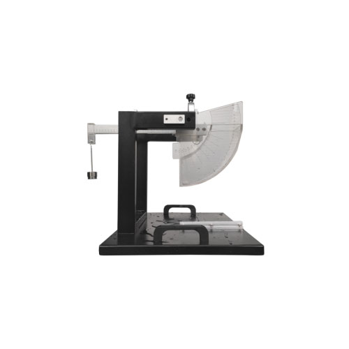
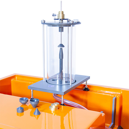
Centre of Pressure Apparatus
AirYa -AYJM34 The Center of Pressure Apparatus
Features:
To be used for finding the centre of pressure of a totally or partially submerged plane surface Should allow students to measure the moment due to the fluid (hydrostatic) thrust on a fully or partially submerged plane, The plane should work in either a vertical or inclined (angled) position The equipment should consist of a vertical panel that holds a clear plastic quadrant, to which students add water The quadrant should have engraved lines to help students keep the plane in a vertical or angled position The cylindrical sides of the quadrant should have their central axis coincidental with the moment measurement axis. Students should be able to measure moment using weights suspended from a level arm A scale on the panel of the apparatus should show the head of water To level the apparatus, levelling feet and spirit (bubble) level should be integrated
The equipment should include non-toxic water dye to help students see the water levels more clearly and a syringe for Specification investigation of the hydrostatic pressure in fluids at rest tiltable water tank with fill level scale lever arm with different weights Technical data Water tank inclination angle: 0°…90° content: 0…1,8L scale: 0…250mm effective area, max. 75x100mm Lever arm max. length: 250mm Weights1x 2,5N1x 2N2x 1N 1x 0,5N Dimensions and weight LxWxH: 400x500x450 mm |
Weight: approx. 12kg
.jpg)
Discharge Over a Notch
Airya-AYDON46-Discharge Over a Notch
Features:
? A tank and set of notch wiers for the study of flow regulation and measurement devices
? Portable, corrosion-resistant glass-fibre channel for ease of use and long life
? Should include one rectangular and two V-shaped notches for basic experiments
? Two additional weirs should be included for more advanced experiments
? Adjustable depth gauge for precise measurement of water level
? The apparatus should show clearly the use of weirs as simple flow regulators
? Each weir should fit in a sealed groove in the channel section
? Water should flow through the channel and over the weir, where the deep tank exit allows students to see the discharge
? Students should be able to measure the free water surface using an adjustable depth gauge attached to a beam across the channel
? Experimental Capabilities:
? Comprehensive study of flow over weirs, including:
? Investigation of head against discharge
? Coefficient of discharge
? Rectangular and different angled V-notches
? Technical Parameters:
? Rectangular Notch Weir Depth: Minimum 100mm
? Rectangular Notch Weir Width: Minimum 30mm
? V Notch Weir:
? One of depth 100mm (min.) and 30° angle
? One of depth 100mm (min.) and 90° angle
? Cipoletti Notch Weir:
? Depth 100 mm (min.), width at top of notch 30 mm (min.), width at base of notch 25 mm (min.) and thickness 3mm (min.)
? Linear Head/Flow Notch Weir:
? 3mm thickness and 85mm depth (min.) |
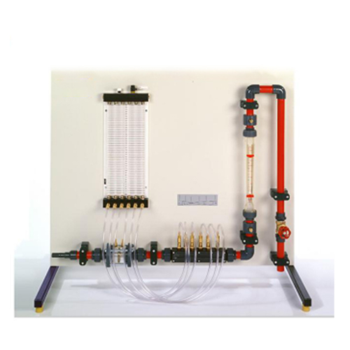
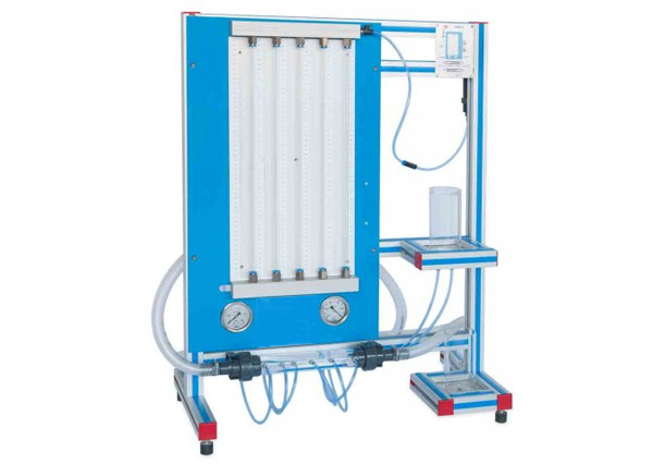
Flow Measurement Methods Apparatus
AIRYA-AFF134 Flow Measurement Methods Apparatus
Learning Objectives / Experiments flow measurement with orifice plate flow meter and measuring nozzle ,Venturi nozzle rotameter pressure measurement with Pitot tube comparison of different instruments for flow measurement ,determining the corresponding flow coefficients calibrating measuring instruments Specification [1] different methods of flow rate measurement [2] measuring instruments: orifice plate flow meter/measuring nozzle, Venturi nozzle and rotameter [3] 6 tube manometers to determine the pressure distribution in Venturi nozzle, orifice plate flow meter and measuring nozzle [4] measurement of the total pressure with Pitot tube [5] flow rate determined by base module [6] water supply via laboratory supply Technical Data Venturi nozzle: A=84…338mm² angle at the inlet: 10,5° angle at the outlet: 4° Orifice plate flow meter: diameter=14mm Measuring nozzle: diameter=18,5mm Rotameter: max. 1700L/h 6 tube manometers: 390mmWC Dimensions and Weight LxWxH: 1100x672x900mm Weight: approx. 30kg Required for Operation (closed water circuit) or water connection, drain |
.jpg)
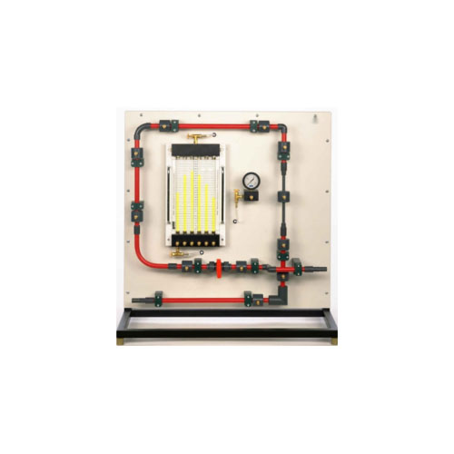
Pressure Measurement Bench
AIRYA-AYJM388 Pressure Measurement Bench
Features:
? Should enable a range of practical investigations into manometer and Bourdon gauge pressure measurement techniques
? The equipment should enable students to fully investigate and compare the operation and characteristics of inclined and U-tube manometers and Bourdon-type vacuum and pressure gauges
? It also should include a separate Bourdon gauge with dead-weight calibration apparatus, enabling clear observation of the Bourdon tube mechanism
? The apparatus should consist of two units:
? A manometers and gauges unit
? A Bourdon pressure gauge calibration unit Specification Manometers and Bourdon gauges are fundamental pressure-measuring devices. They are intrinsic parts of more complex measuring instruments, such as pneumatic comparators and flow indicators. It is important therefore that students fully understand their operation, characteristics and principles of calibration. Pressure Measurement Bench enables students to fully investigate and compare the operation and characteristics of inclined and U-tube manometers, and Bourdon-type vacuum and pressure gauges. It also includes a separate Bourdon gauge with dead-weight calibration apparatus, enabling clear observation of the Bourdon tube mechanism. The apparatus consists of two units: A manometers and gauges unit A Bourdon pressure gauge calibration unit The manometers and gauges unit is a framed structure with a backboard, holding a:vertical U-tube manometer, U-tube manometer with an inclined limb, Bourdon gauge for measuring vacuums, Bourdon gauge for measuring positive pressure, and, syringe assembly for pressurizing and reducing pressure Comparison of pressure measurement by manometer and Bourdon gauge Calibration of a pressure gauge Determination of gauge errors as a function of true pressure |
Friction Loss in a Pipe
AIRYA-AYJM32 Friction Loss in a Pipe
AYJM32 Instrument to Measure Friction Losses in Pipes Should directly measure friction loss in a small bore test pipe
? Capable of investigating laminar and turbulent flow and the transition point
? Capable of showing the critical Reynolds Number and verifies Poiseuille's Equation for laminar flow
? Should include precision valve for precise flow control and a header tank for good laminar flow
? Test pipe internal diameter: 3mm (minimum)
? Water manometer range: 0 ~ 530mm
? Pressure meter range: 0 ~ 20m (water)
? Required accessories: Pressure meter, hand-pump, stopwatch and printed operation manual
? Hydraulics Data Management System Software:
? Simple software tool for manual data entry and recording of data for hydraulics experiments
? Intuitive and easy-to-use, with clear, customisable display and layout options Main parts: • Smooth pipes of various” lengths and internal diameters Artificially roughened pipe • 90-degree elbow • 90-degree smooth bends • Sudden enlargement • Sudden contraction • Gate valve, globe valve and ball valve • Venturi” meter and orifice meter |
• Pitot static tube
.jpg)
Plastic Limit Test
Model: PL 72
Specification: Glass Plate, Palette knives, Air Tight Containers, Spatula, Brass Rod & Porcelain Evaporating Dish. |
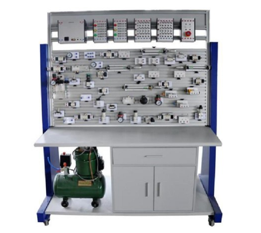
ZMP1104 - Pneumatics Training System
Feature:
Pneumatic training device is at the request of modern pneumatic professional teaching experiment, according to “the hydraulic and pneumatic transmission ", "The Pneumatic control technology", etc., general teaching material contents design. The system in Addition Meet the base and teaching training system of need of practical applications Equipment structure is firm and has good stability Low noise operation layout clear and intriguing design The four truckle with crack slot in order to move and install on the work table. Panel grooves intervals are 25 mm, can easily move all kinds of components insert on it. Various pneumatic components into separate module which is equipped with bottom panel of elastic pins, when training they can build all kinds of pneumatic circuits on general aluminum, fast loading and unloading, flexible layout, clear pneumatic circuit Electrical control units used for independent relay control unit and multi-button unit control electrical, simple and clear! High safety: have over-current protection, the power supply will cut off as earth leakage exceed 30mA; the electrical control use DC 24v power supply, with over current protection, can prevent damage to the equipment caused by improper operation .system nominal pressure is 0.6MPa